6 Meter Direction Agile 3 Element Yagi Antenna
by Don Nelson, N0YE
n0ye@comcast.net
The antenna discussed here is a fixed frequency, 50 MHz, three element Yagi with a special ability to change direction without moving the antenna. This antenna can be switched to have gain in one direction or in the opposite direction by the simple flip of a switch. Simply put the director and the reflector change places when a switch is activated. There are components at the center of the two outer elements that can change the electrical length of the element so that in one configuration the element is electrically longer and behaves as a reflector. In the other configuration, the element is electrically shorter and behaves as a director. The driven element properties are unchanged when the two outer elements are swapped.
Figure 1 shows the general layout of the three elements. Figure 2 is a picture of the antenna. The Yagi was designed using EZNEC antenna modeling software. The dimensions of the antenna were chosen to fit on a 72-inch boom because aluminum tubing is most commonly available in 6-foot lengths. The diameter of the elements was made 0.250 inches because that size of aluminum rod was also available. Smaller diameter elements are subject to being accidentally bent. Larger element rods will present a tradeoff of added weight vs sturdier antenna structure. The modeling software suggests this antenna should have a forward gain of 7.5 dBi and a front-to-back radio of 15 dB.
The two outer elements are made up of a pair of element halves. Each element half is attached to a metal block which in turn is attached to the boom via an insulating piece of Delrin plastic. This is a mechanically sturdy structure while at the same time allowing the element halves to be insulated from the boom. The four element halves are the same length so that looking at the antenna there is no evidence as to which is the forward direction or reverse direction of the antenna. The metal blocks for this antenna are 0.5 by 1.0 by 1.25 inches. The metal blocks are attached to the Delrin with an inside distance between the blocks of 2.75 inches
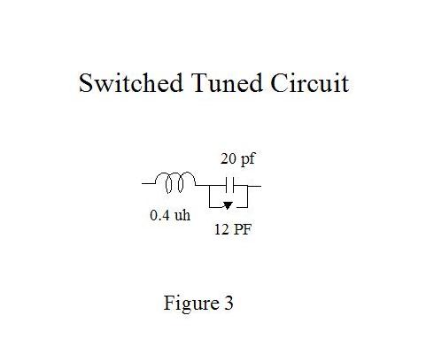
The circuit that connects the pair of element halves is made up of a coil and a capacitor in series as shown in Figure 3. At 50 MHz the tuned circuit presents effectively a short between the two element halves. This configuration makes the element a director. A relay is connected across the capacitor to short the capacitor when the contacts are closed. When the contacts are closed, the coil is in series with the element halves and makes the element electrically longer and thus makes the element a reflector. Figure 4 shows a close up picture of the tuned circuit components and construction.
For the dimensions of the outer elements of this antenna, the inductance of the coil was determined to be about 0.4 micro henry. If the element dimensions were to change, the inductor value will change as well. The coil is fabricated using number 10-gauge copper wire wound on a 1-inch cylinder. The resulting coil is 1.06 inches ID. The coil has 3 turns a coil length of 0.6 inches. The lengths of the wire extending away from the coil to the elements add the total inductance of the coil. The length of wire to and from the relay also adds to the circuit inductance. So the dimensions of the mechanical components (Delrin, metal blocks, etc.) will affect the tuned circuit.
The open contacts of the relay add capacitance to the circuit. The relay needs to be chosen such that the capacitance is not too large. The relay chosen for this antenna is a readily available inexpensive plug-in automotive 30-amp relay that had an open contact capacitance of about 12 pf. The tuned circuit was hand tuned by adding additional capacitance in parallel with the relay contacts. For this antenna, the added capacitance is 20 pf.
Tuning the antenna to the 50 ohm coax was done using a gamma match circuit. The rod extending from the center conductor of the coax is 3/32 hobby brass 2.5 inches above the element and extends 10 inches along the element. The adjustable portion of the gamma match is 5 inches of 7/32 hobby brass. Shrink-wrap tubing was used as the insulating material on the 3/32 hobby brass. The gamma match is delicate matching method and requires tuning each time I move the antenna. Another matching scheme is going to be considered.
This antenna was used during the 2010 Field Day with favorable results. Located on high ground with very good 360-degree horizon, I was able to hold a frequency and have a modest pileup using all of 50 watts. The front-to-back ratio is probably better than the model suggests and the side nulls are very deep. The forward gain is good but unknown until I can compare the antenna to a standard gain antenna.


